I'll make no disclaimers here about safety, techniques...you know the drill.
This is just a little photo session to make things more comfortable for anyone
nervous. You should also get a spec sheet on the LM3875 and Will Page's excellent
doc on the mod. You can e-mail me at BBelloff@optonline.net
and I will provide both.
I left the chassis in the amp and the amp sitting in its stand, it was very convenient.
Unsolder all of the connections to the small PC board attached to the chip. Remove
the TDA 2050 amplifier chip, ribbon cable, and capacitor from the board. Unscrew
the TDA 2050 from the heat sink.
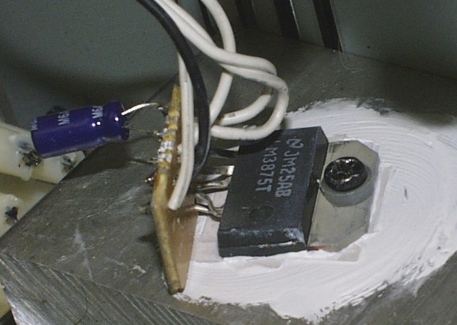
You will only need pins 1,3,4,7, and 8 for the new chip. I broke all of the
others off. Um, I also broke pin 8 off chip #1. You are looking at chip #2 (buy
an extra or two-the pins can be delicate).
I bent the pins on the new chip to fit the holes on the old PC board. Looking
at the 5 holes for the chip, from the circuit side (not the chip side) , I slowly
and carefully bent the pins to fit the 5 holes as follows:
|
1
|
3
|
8
|
||
|
4
|
7
|
I then soldered the pins to the board and trimmed the excess.
They can not be bent to fit in the proper order, so the ribbon cable's wires get soldered back on in DIFFERENT locations! Pay attention to the re-ordering, re-check yourself, and check yourself against the instructions from Will. He lays out the pin order in his doc.
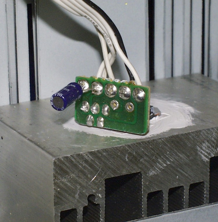
Now to solder the ribbon back on. Again looking at the PC board from the circuit side, not the chip side, I put them back in this order, left to right:
C/W - 1
D/W - 2
E/W - 3
A/W - 4
B/W - 5
I then soldered the cap directly to #s 1 and 2 (- to 1).
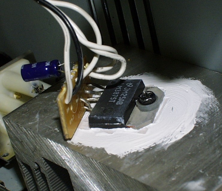
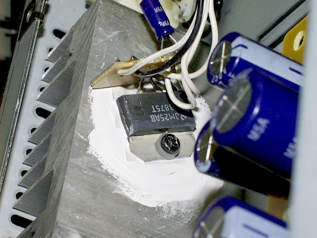
I had a larger mica insulator under my chip- I was able to reuse it. If you don't, get a mica insulator from Radio Shack or wherever. Unless you order a LM3875TF (isolated), you MUST use a mica insulator between the chip and heat sink. It's like a very thin plastic sheet, easily trimmed. Use heat sink paste between the chip and the sink as well. It's a must for proper heat transfer (Radio Shack or CompUSA).
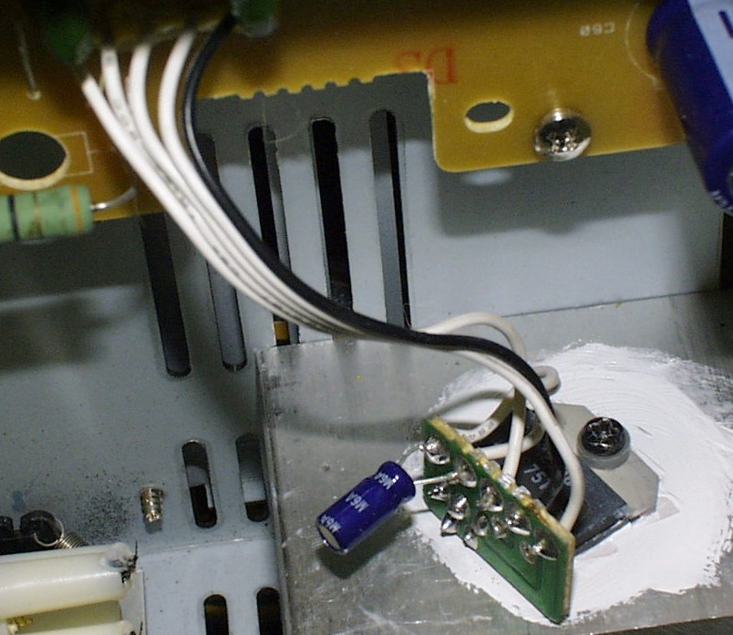
That's it. The rest should be intuitive. I have here a few more shots of the
chip, and one shot of the whole amp. Hope you like it.
 |
 |
All original material contained in the sites
listed on this page
is copyrighted © 2002 PDittyProductions
![]()